raspberry pi optocoupler output schematic Resistor in series with optocoupler output
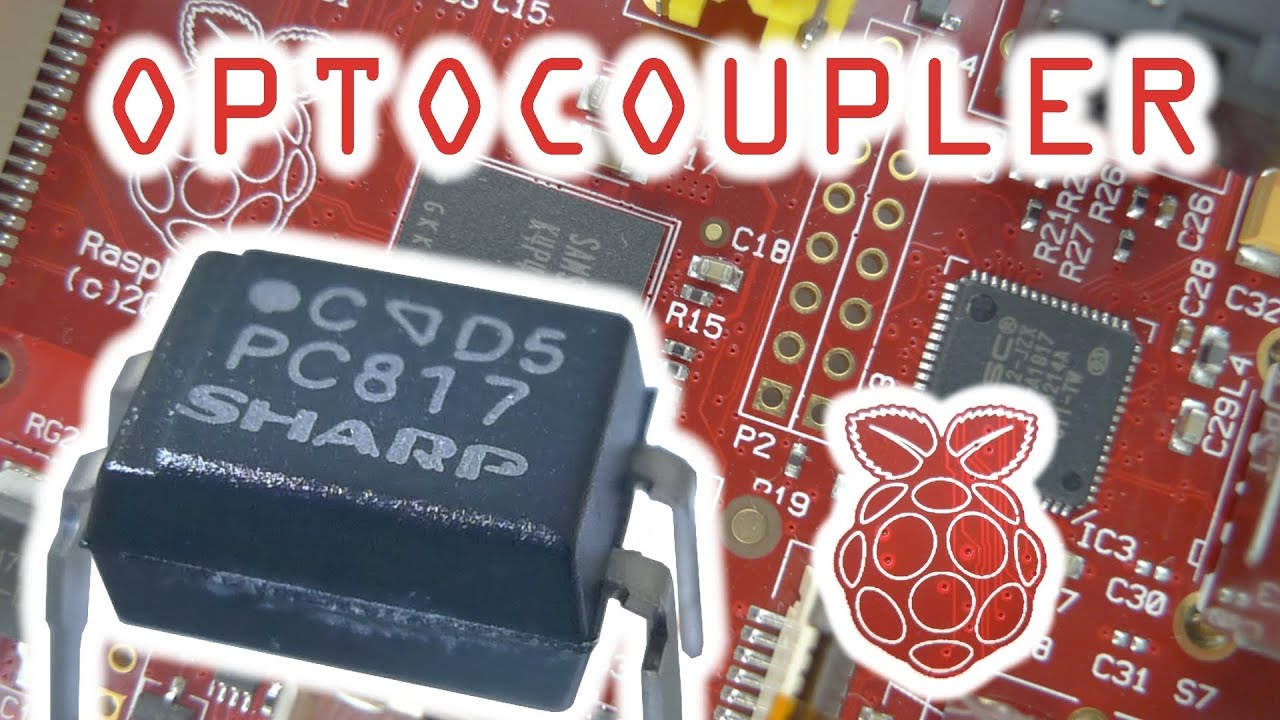
Alright folks, gather 'round! We've got some technological wizardry brewing, the kind that makes your circuits sing and your microcontrollers dance... maybe not literally, unless you've got some serious servo action going on. Today, we're diving into the murky, yet strangely satisfying, depths of optocouplers. Think of them as the unsung heroes of electrical isolation – the bouncers at the nightclub for your sensitive electronic components.
Optocoupler schematic/diagram - Arduino Forum

Ah, the noble schematic. This diagram here... well, it's trying its best to be helpful. It's like that friend who tries to explain quantum physics using only hand gestures and vaguely defined metaphors. You appreciate the effort, even if you're still mostly lost. Just look at those lines crisscrossing each other, little electrical pathways whispering sweet nothings to each other. You've got your resistor, diligently resisting. You've got your LED, emitting light with all the vigor of a tiny, electrically-motivated sun. And of course, the transistor, switching things on and off faster than you can say "Boolean algebra."
Seriously though, optocouplers are pretty neat. They let you control a circuit using light, which means you can isolate your microcontroller from potentially dangerous voltages. Imagine your Arduino, happily blinking away, completely oblivious to the high-voltage shenanigans happening on the other side of the optocoupler. It's like having a bulletproof window between your precious electronics and the wild, untamed wilderness of power supplies and AC currents. Think of it as digital social distancing, keeping your sensitive bits away from potentially electrifying situations.
Help with 24VAC to RPi 3.3 Optocoupler - Raspberry Pi Forums

Now, this diagram…This one is a doozy! We're talking about wrangling 24VAC – that's Alternating Current, the kind that makes your hair stand on end (in a bad way, usually) – down to a manageable 3.3V for a Raspberry Pi. It’s like trying to tame a wild badger with a feather duster. Risky business, but with the right components, it’s perfectly achievable.
You've got the bridge rectifier, turning that alternating current into a pulsating DC beast. Then you have the resistors, bravely limiting current. The optocoupler then swoops in for the rescue, elegantly keeping the Raspberry Pi safe. The Raspberry Pi, meanwhile, sits serenely, unaware of the electrical gauntlet it narrowly avoided. It’s probably busy calculating the digits of Pi or maybe controlling a robotic arm, totally oblivious to the voltage drama unfolding nearby.
So there you have it! Two diagrams, two slightly different scenarios, but the same fundamental principle: using optocouplers to keep things safe and sound. Now, go forth and electrify responsibly! Just remember to double-check your wiring, triple-check your voltage ratings, and always wear your imaginary Faraday cage helmet. Because in the world of electronics, a little bit of caution can go a long way.
If you are searching about Resistor in series with optocoupler output - General Electronics you've visit to the right place. We have 25 Pics about Resistor in series with optocoupler output - General Electronics like Optocoupler - transistors 12v - Raspberry Pi Forums, Optocoupler working from 3v3 but not from GPIO. - Raspberry Pi Forums and also [Noob question] Can you use an optocoupler to act as a button for input. Here you go:
Resistor In Series With Optocoupler Output - General Electronics
 forum.arduino.cc
 Help With 24VAC To RPi 3.3 Optocoupler - Raspberry Pi Forums
 forums.raspberrypi.com
 Optocoupler Schematic/diagram - General Electronics - Arduino Forum
 forum.arduino.cc
 Opto-isolated Relay Connection - Raspberry Pi Forums
 forums.raspberrypi.com
 Using Optocouplers With The Raspberry Pi - YouTube
 www.youtube.com
 raspberry pi optocouplers
Opto Isolator - Optocoupler Input Or Encoder Output Problem
 electronics.stackexchange.com
 Transistors - Drive Relays With Optocoupler And A Raspberry Pi
 electronics.stackexchange.com
 pi raspberry optocoupler drive relays questions followings electrical stack
How To Use Optocoupler With Raspberry Pi Pico W | Raspberry Pi Pico W
 www.youtube.com
 Optocoupler Read And Write Circuit With Raspberry Pi - Raspberry Pi Forums
 forums.raspberrypi.com
 HLT Control, Hardware - Raspberry Pi - UnCraft
 www.uncraft.co.uk
 raspberry gpio optocoupler circuit hlt hardware
3 Schematic Of Optocoupler | Download Scientific Diagram
GitHub - Gamename/raspberry-pi-pico-optocoupler: Use Opto-couplers On A
Interconnectivity Of Optocoupler And Raspberry Pi | Download Scientific
 www.researchgate.net
 Opto Isolator - Cannot Isolate Raspberry Pi From The Other Circuit
 electronics.stackexchange.com
 Optocoupler Working From 3v3 But Not From GPIO. - Raspberry Pi Forums
 forums.raspberrypi.com
 Raspberry Pi Optocoupler Power Detector - OSHWLab
 oshwlab.com
 Interconnectivity Of Optocoupler And Raspberry Pi | Download Scientific
 www.researchgate.net
 HLT Control, Hardware - Raspberry Pi - UnCraft
 www.uncraft.co.uk
 optocoupler relay circuit hlt raspberry output
Circuit Diagram Arduino To Optocoupler
 schematicpigskins.z14.web.core.windows.net
 Raspberry Pi: Optocoupler To Control Pi Power Supply - YouTube
 www.youtube.com
 [Noob Question] Can You Use An Optocoupler To Act As A Button For Input
![[Noob question] Can you use an optocoupler to act as a button for input](https://europe1.discourse-cdn.com/arduino/original/4X/e/8/e/e8e474f54a80f0aef4552b8e43cd11acd881498b.png) forum.arduino.cc
forum.arduino.cc Optocoupler Read And Write Circuit With Raspberry Pi - Raspberry Pi Forums
 forums.raspberrypi.com
 Optocoupler Use For Relaying A Robotino Digital Signal To The Raspberry
Raspberry Pi Archives - Kitflix
 kitflix.com
 Optocoupler - Transistors 12v - Raspberry Pi Forums
 forums.raspberrypi.com
 Raspberry pi archives. Using optocouplers with the raspberry pi. Raspberry pi: optocoupler to control pi power supply